The way out of this is by leveraging frequencies. A knock event ringing inside the cylinder produces a vibration at a specific, predictable frequency. If you calibrate your detection system to listen at that frequency, and reject everything else, then knock comes through clearly while the background noise gets filtered out. Sounds ideal and, thankfully, the frequency you need is very closely correlated to the bore diameter of the engine.
This article covers why bore diameter sets the frequency, how to calculate it, which resonant mode to start with, and how to use the calculated number in practice.
What's actually vibrating
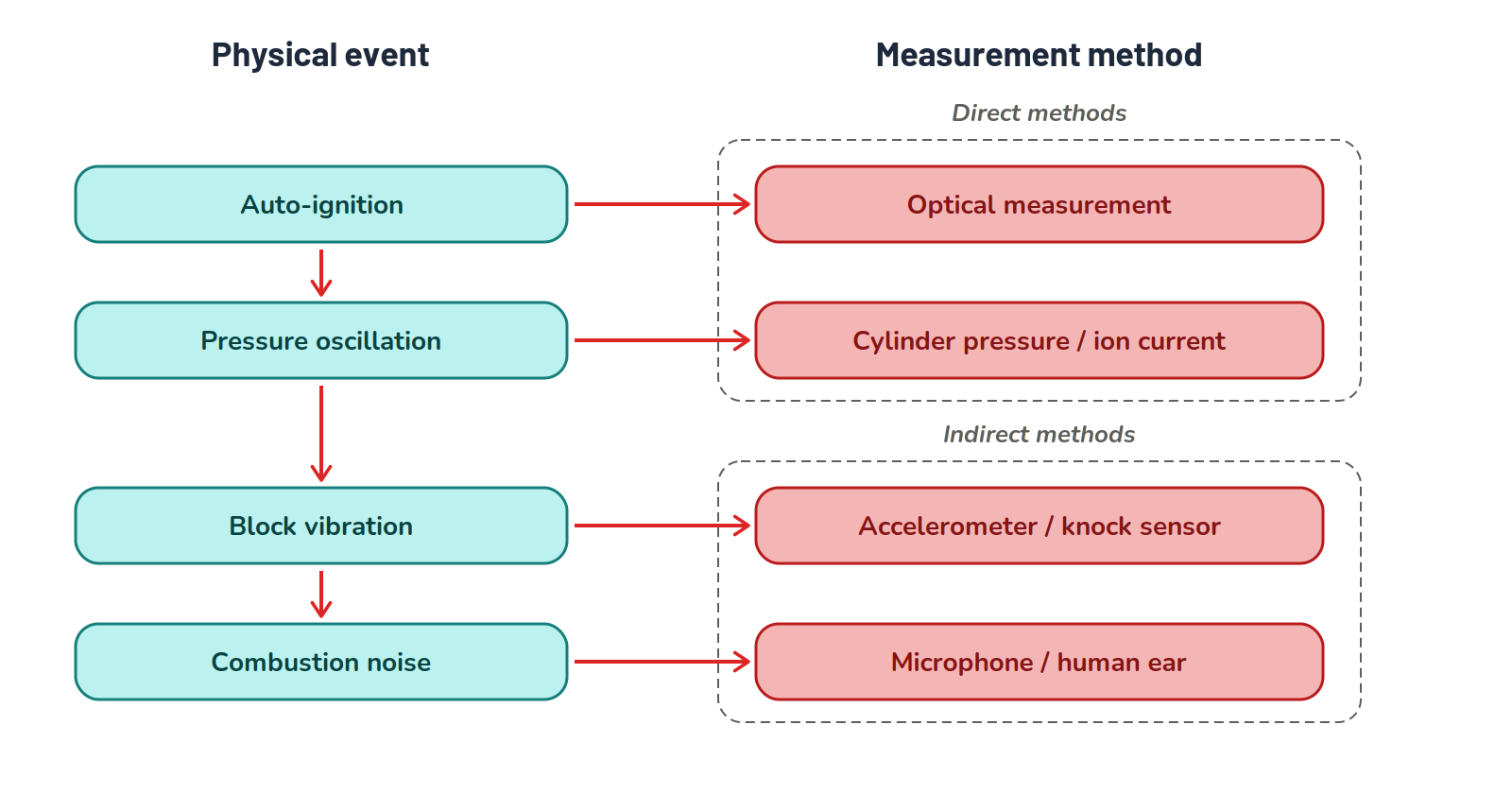
A knock event is the autoignition of the end-gas ahead of the flame front, with the variables that move the knock threshold determining when or if this happens. Because of the spontaneous and rapid heat release from knock, large pressure spikes send shock waves reverberating across the cylinder, creating the characteristic 'pinging' or 'knocking' sound associated with this type of abnormal combustion.
That shock wave reflects off the cylinder walls and continues bouncing back and forth. The rapid oscillations visible on an in-cylinder pressure trace during a knock event are exactly that wave reverberating in the cavity.
Those oscillations are what we want to detect. Not the pressure spike itself, but the ringing that follows.
Why bore diameter sets the frequency
The cylinder during combustion is a closed cavity with gas inside. When you hit it with a pressure spike, it rings at frequencies determined by its geometry, like a musical triangle would ring out when it's struck. Because the pressure spike is contained, the wave reflects between the walls, and the time it takes to travel back and forth across the cylinder determines the period. The period tells us the frequency.
Bore diameter sets the distance the wave has to travel. Smaller bore, shorter distance, faster oscillation, higher frequency. Larger bore, longer distance, lower frequency, all pretty straightforward.
Essentially, if you change the bore size, the frequency moves with it.
Another useful analogy is a guitar string. Pluck a thick string and it vibrates slowly and sounds low. Pluck a thin one and it vibrates fast and sounds high. The cylinder isn't a string, but the relationship between physical size and resonant frequency is the same.
There is no single 'knock frequency' for an engine. The bore sets a family of resonant frequencies, and the right one to listen for is whichever cuts cleanest through engine noise.
The formula and what each input does
The knock frequency is calculated from three values. We use the Greek letter Rho (ρ) for the wave mode constant, which describes the resonant pattern you're solving for. The speed of sound through the gas inside the cylinder is marked "c", and D is the bore diameter.
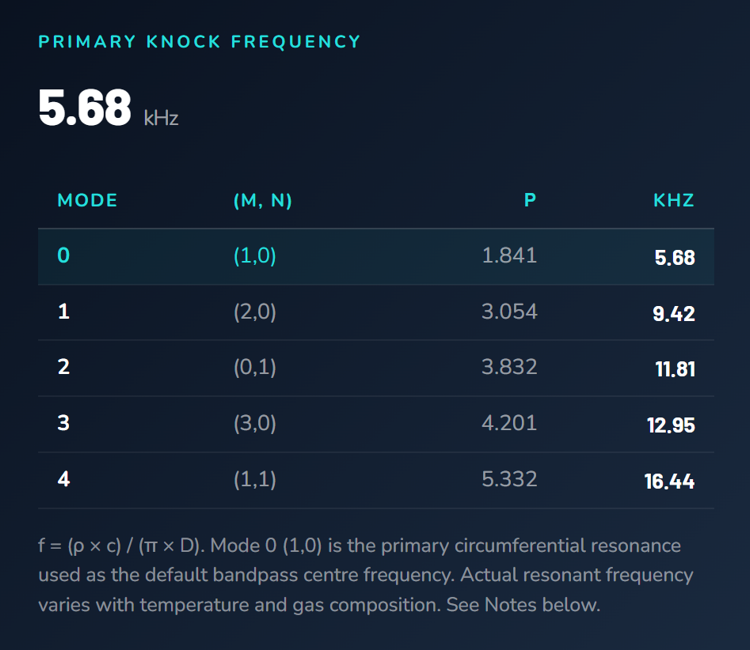
f = (ρ × c) / (π × D)
The wave mode constant (ρ) exists because a cylinder doesn't ring at one frequency only. It rings at a series of related frequencies, each corresponding to a different way the pressure wave can fit inside the cavity or combustion chamber. The lowest of these is the primary mode, with ρ = 1.841. Higher modes correspond to higher frequencies and different geometric patterns.
The speed of sound (c) is set by the temperature and composition of the gas in the cylinder. A common starting value is 1000 m/s, which works well across most spark ignition engines burning gasoline or ethanol blends. Combustion conditions will shift this value around a bit in practice, which is one reason the calculated frequency is always a starting point rather than a final answer.
The bore diameter D is the only input you can read directly off the engine. With ρ and c held fixed, frequency is inversely proportional to D, which just means that as bore increases there is a proportional decrease in frequency. Double the bore and the frequency halves. This inverse relationship is the reason a 4-cylinder Honda K20 and a small-block V8 sit in noticeably different frequency bands, even when both are running pump fuel and similar combustion temperatures.
Modes. Mode 0 first, Mode 2 when noise overlaps
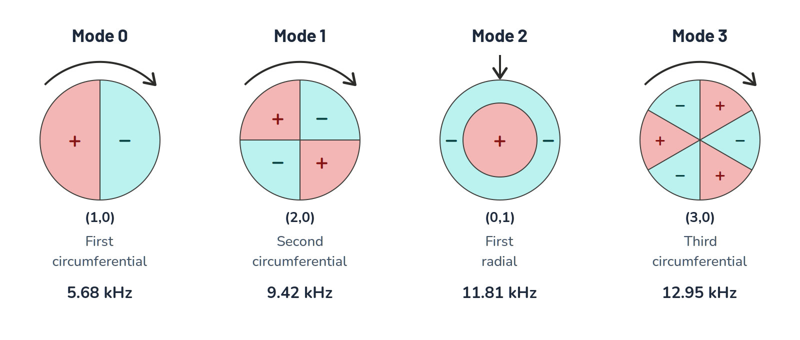
There are five resonant modes you'll typically work with. Mode 0 (ρ = 1.841) is the primary circumferential mode and produces the strongest signal in most cases. Mode 1 (ρ = 3.054) is the second circumferential mode. Mode 2 (ρ = 3.832) is the first radial mode. Modes 3 and 4 are higher-order patterns used less often.
Start with Mode 0 as the default. It tends to give the highest signal strength and the cleanest separation from background engine noise. If the signal-to-noise ratio is acceptable, you don't need to look further. Signal-to-noise ratio is just describing how clearly you can 'hear' or detect knock above the background noise of the engine in operation, and the higher the better.
Where Mode 0 starts to fail is when something else in the engine happens to vibrate at or near the same frequency. Valve events, injector clicks, and mechanical resonances in cams, lifters, and timing components can all overlap the frequency band you're trying to listen in. The result is either false knock, where the detection system reports knock that isn't actually happening, or masking, where real knock gets buried in the noise.
Mode 1 is the easy first try if Mode 0 is contaminated. It's still circumferential, so you're listening at a higher harmonic of the same physical resonance.
If both circumferential modes are noisy, switch to Mode 2. Mode 2 is the first radial mode, which is a fundamentally different geometric pattern. The wave is propagating inward and outward from the cylinder axis rather than around the perimeter, so it's less likely to share a frequency band with mechanical noise sources whose geometry is rotational. When valvetrain or rotating-component noise is dominating the circumferential modes, the radial mode often cuts through where they can't.
Start with Mode 0. Move to Mode 2 when circumferential noise contaminates the signal. The radial mode comes from a different physical pattern and often clears the band.
Worked examples
The Knock Frequency Calculator takes the bore size and returns all five modes if you'd rather skip the maths. Otherwise, let's put two different engines through the formula and see what we get.
The GM LS3 has a 103.25 mm (4.065") bore. Plugging that into the formula with ρ = 1.841 and c = 1000 m/s gives a Mode 0 frequency of 5.68 kHz. Mode 1 lands at 9.42 kHz, and Mode 2 at 11.81 kHz.
The Honda K20 has an 86 mm (3.386") bore. Same formula, same speed of sound. Mode 0 is 6.81 kHz, Mode 1 is 11.30 kHz, and Mode 2 is 14.18 kHz.
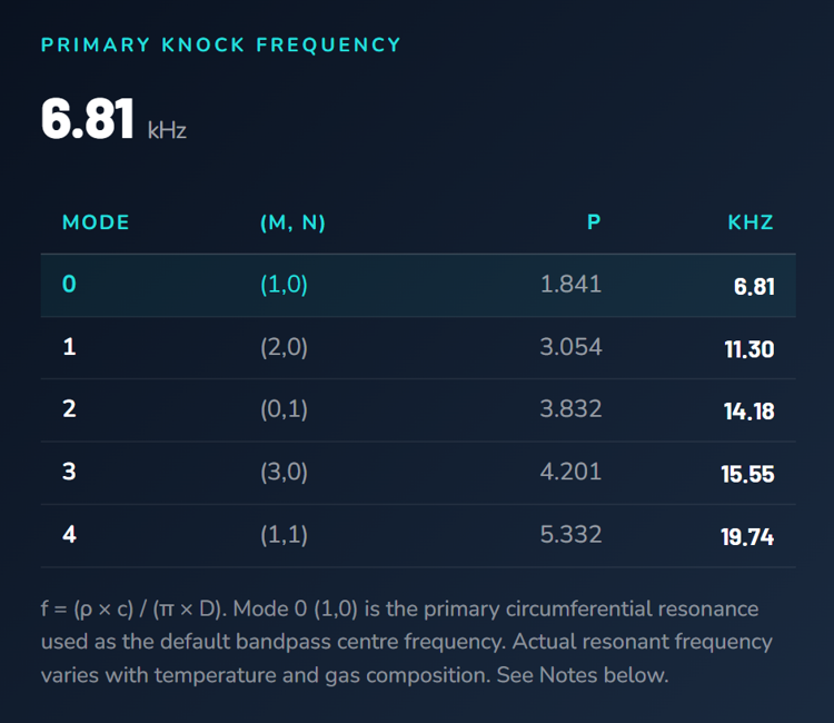
Two patterns are visible. First, the smaller bore produces a higher frequency at every mode. That's the inverse relationship between bore diameter and frequency playing out. Second, the higher modes climb quickly. Mode 2 sits roughly twice as high in frequency as Mode 0 for the same engine.
Most aftermarket knock monitors and ECUs let you set the centre frequency for a bandpass filter. Enter the Mode 0 value to start, then test on the engine.
Why the calculator output is a starting point
Two factors push the actual knock frequency away from the calculated value.
The first is the speed of sound. The 1000 m/s default is an average. The actual value depends on the temperature and composition of the gas in the cylinder at the moment knock occurs, and that varies with combustion conditions. In practice this shifts the real frequency by something on the order of 10 to 20 percent around the calculated value.
The second is engine structure. The vibration travels from the combustion chamber through the cylinder block and head to the sensor. The path it takes affects what reaches the sensor. Sensor placement, mounting quality, block stiffness, and other structural details all influence the frequency content that gets picked up.
The calculator gives you a centre frequency. The real one sits in a band around it. Test plus or minus 0.5 to 1.5 kHz from the calculated value to find where the signal is cleanest.
Treat the calculator output as a starting band rather than a single number. The right value is whichever produces the cleanest signal under the conditions you actually run.
Set your filter at the Mode 0 value and listen for knock under controlled conditions. If the signal is clear, you're done. If it's marginal, step the centre frequency up and down by 0.5 kHz and test again. Walk out to plus or minus 1.5 kHz before changing modes.
If a clean signal can't be found within the Mode 0 band, repeat the same process at the Mode 1 frequency, then at Mode 2 if necessary. Mode 2 is your strongest fallback because it comes from a different physical resonance and not just a higher harmonic of the same one.
Setting up the sensor channel
Frequency selection is one part of the system. Sensor placement and mounting are the other. A correctly tuned filter can't recover a signal that never reached the sensor.
Place the sensor high on the block, close to the head deck, between the middle cylinders if the engine is an inline configuration. This puts it as close to the source of vibration as possible while giving roughly equal access to all cylinders. On a V engine, fit one sensor per bank.
The mounting surface needs to be flat and clean. Vibration transfers through metal-to-metal contact, so any paint, gasket residue, or surface irregularity reduces what reaches the sensor element. If a suitable mounting boss doesn't exist, a custom boss machined to match the block contour and bonded with high-temperature epoxy works well for development engines that will see repeated testing.
Torque the sensor to the manufacturer's spec. Most aftermarket knock sensors call for around 20 Nm. Over-tightening can damage the sensor or strip the threads, while under-tightening leaves the sensor mechanically loose, which collapses the signal-to-noise ratio. Be sensible here.
Frequency selection, sensor placement, and mounting all contribute to signal-to-noise ratio. Get any of them wrong and the others can't fully compensate.
Once the sensor is mechanically installed, set the bandpass filter to the Mode 0 frequency calculated from your bore diameter, listen to the engine under known no-knock conditions to establish a noise baseline, and then advance timing or run conditions where knock is expected. Walk the filter frequency up and down within the band as needed until knock is clear and the noise floor is low, and that's it, you're set up and ready for your calibration session.
Key points
- A knock event excites a resonance inside the cylinder cavity that rings at a frequency set primarily by bore diameter
- The frequency is calculated from f = (ρ × c) / (π × D), where ρ is the wave mode constant, c is the speed of sound in the cylinder gas (typically 1000 m/s), and D is the bore diameter in metres
- Mode 0 (ρ = 1.841) is the primary circumferential mode and the default starting point for the bandpass filter centre frequency
- Mode 2 (ρ = 3.832) is the first radial mode and the strongest fallback when circumferential modes overlap with engine noise sources
- The calculated frequency is a starting point. Combustion conditions and engine structure shift the real value by something on the order of 10 to 20 percent
- Test plus or minus 0.5 to 1.5 kHz around the calculated value to find where the signal is cleanest before stepping to a different mode
- Sensor placement, mounting surface preparation, and correct torque all determine what the filter has to work with
Related Resources
Dialling in a detection channel is one piece of a larger job. Managing knock as a complete strategy, where detection feeds into your timing decisions, your compensations, and how the engine is handled across changing conditions, is what Stage 3 of the Calibration Competence and EFI Master Programs is built around. The Programs develop that through a structured progression, with the depth to carry over to engines and problems you haven't met yet. Take the free assessment to find out which Program fits your goals.
Find Your ProgramGet notified of new articles
One article per week on EFI fundamentals, calibration principles, and diagnostic thinking. No spam.
You're subscribed. We'll let you know when new articles are published.