This article covers what the sensor is measuring, what that measurement represents, what the ECU does with it, and what happens across all of those strategies when the conversion is off.
The ECU never receives a temperature
A coolant temperature sensor is a thermistor, which is just a resistor whose resistance changes with temperature, and as the name suggests they sit in a threaded housing that locates the tip of the sensor in the coolant stream. Almost every one you're likely to encounter is an NTC type, or Negative Temperature Coefficient, which just means resistance comes down as temperature goes up, and vice versa.
The ECU provides the sensor with a steady supply voltage, usually 5 volts, and reads the signal voltage that comes back. As the sensor warms up its resistance falls, and the signal voltage falls with it.
The ECU takes the varying input voltage and this is converted into a temperature that we can read and interpret via the sensor calibration curve, that maps temperature to voltage. Every part of the calibration that takes coolant temp as an input then works with this conversion by virtue of the fact that we calibrate based on temperature, not voltage.
The sensor reports a voltage. The sensor calibration curve is the only thing that turns it into a temperature, and that temperature is what every coolant temperature referenced table in the ECU uses.
Why the curve isn't a straight line
Resistance doesn't fall in even steps as the temperature of the sensor increases. This is just a function of the sensor construction. The relationship between temperature and resistance is therefore non-linear, meaning it's not a simple straight line relationship.
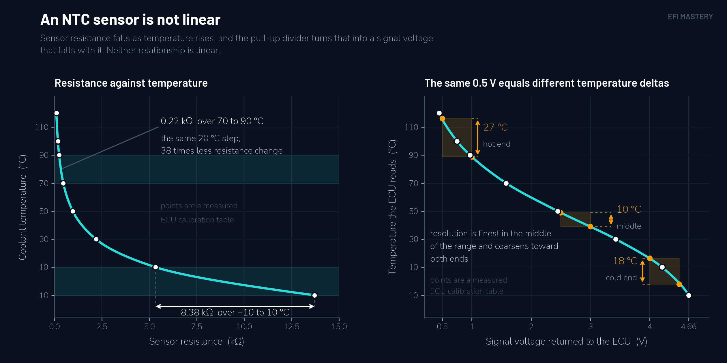
Different sensors have different curves, and two sensors that thread into the same hole and both read correctly at 90°C (194°F) can be a long way apart at 10°C (50°F). That's why we need to ensure we have the correct sensor data setup in the ECU, or if we're manually entering values then these need to accurately detail the voltage values at several temperatures. Remember that the curve for a different sensor is different, so always confirm your sensor calibration data or refer to the sensor manufacturer's data sheet. Getting this wrong can throw your calibration out across seasons, or even simply changing the sensor for one with the correct data can highlight issues, as the previous calibration had errors baked into it.
The curve isn't a conversion detail buried in the setup pages. It's the definition of temperature that every table referencing it works from. Make sure your sensor calibration data is accurate. If no data is available, do the testing and collect your own data. Just be accurate.
What the number represents
What we don't often consider is why we measure coolant temperature in the first place. Coolant temperature is a proxy for engine temperature, which is the thing we actually care about because of the impact that varying temperatures have on the efficiency and effective operation of an engine. The coolant runs through passages in the block and the head, in direct contact with a large part of the engine, picking up heat from all the various components as it goes. What reaches the sensor is essentially a bulk average of these components.
That average tracks the engine as a whole, which is why every ECU tends to use it. It gives us a very good understanding of where the engine is at, temperature wise. The cylinder head itself, though typically runs 4 to 8°C (8 to 15°F) hotter than the coolant, so with 90°C (194°F) coolant temp on the screen the head is sitting at something like 94 to 98°C (201 to 208°F).
Coolant temperature is an average across the whole engine. That's what makes it useful, and it's why no single part of the engine is actually at that temperature.
Almost everything an ECU does is coolant temperature referenced
There's more going on behind this one sensor input than most people expect.
Compensation tables carry engine temperature on one axis, and the extra fuel or timing changes they command changes as the engine goes through the warm up process. The priming pulses and post-start enrichment is also directly referenced against coolant temperature.
Most ECUs let you set target idle against coolant temperature as well, and it's common to see something in the order of 400 rpm above the nominal target when coolant is close to 0°C (32°F). Idle speed then reduces smoothly back to normal as the engine warms up. The higher target does a couple of things. It helps the engine hold a stable idle against the extra friction, and putting heat into the block faster.
Ignition timing carries a correction from the same input. The main timing numbers come from your speed and load table, then further adjustments are applied with respect to coolant temperature and inlet air temperature. Timing is typically added at low temperature where the mixture tends to burn slower. Coolant temperature is also one of the variables that moves your knock threshold around, so on the hot side of the range the ignition correction is often made in the opposite direction, to preempt knock.
Charge temperature correction in some ECUs leverages the coolant temperature sensor as well. Air entering the cylinder is warmer than what your IAT sensor measured, because it picks up heat crossing the throttle body, the manifold, and the port. How much warmer depends on how hot the engine is and how far the intake charge has to travel after the air temperature sensor. More capable ECUs carry a set of tables describing that heating as a function of coolant temperature and airflow. That correction feeds straight into the airflow estimate, and from there into the fuel calculation.
At the hot end of engine operation, fan control is usually the simplest output on the ECU, a turn-on set point above the thermostat's control temperature, and a turn-off set point either as its own temperature or as a hysteresis band a fixed number of degrees below the turn on point.
Beyond that sit all of the engine protection strategies. Things like raised idle to move more coolant, and richer fuelling at high engine temperature, with timing and boost limits on top of that in a lot of setups.
Then there's your own working conditions when you're tuning, which are referenced to it as well. The base airflow model gets built with the engine warm and stable, specifically so the temperature compensations aren't interfering while you're working. Most of an engine's life is spent in a fairly narrow band, roughly 82 to 100°C (180 to 212°F) with a working thermostat and radiator, and that band is where your VE table gets populated.
What all of these strategies assume, is that the relationship between voltage or resistance and temperature is correct. The temperature value we look at constantly on the laptop screen during a tuning session is also at the mercy of the sensor calibration. Remember, the ECU is reading voltage, the temperature value comes from the calibration curve, and if that's wrong, so is the number you're staring at on the screen.
A wrong curve is not a constant offset
So let's be specific about what goes wrong, because "the sensor calibration is out" is vague enough to be useless.
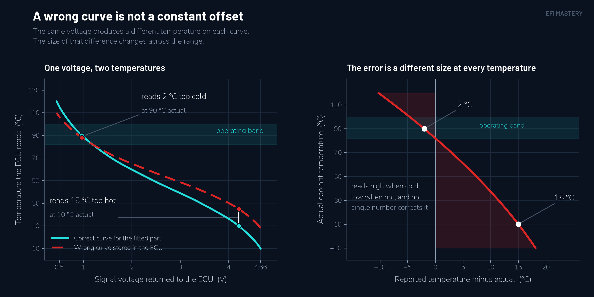
The error is the difference between the temperature the ECU calculated from the returned voltage and the actual temperature of the coolant at the sensor tip. Call it a conversion error. It's not a fault, in the sense that nothing is broken and no wire is damaged. The sensor is working exactly as it should, returning the voltage its resistance produces, and the ECU is converting that voltage exactly as instructed. It's just that the conversion is wrong.
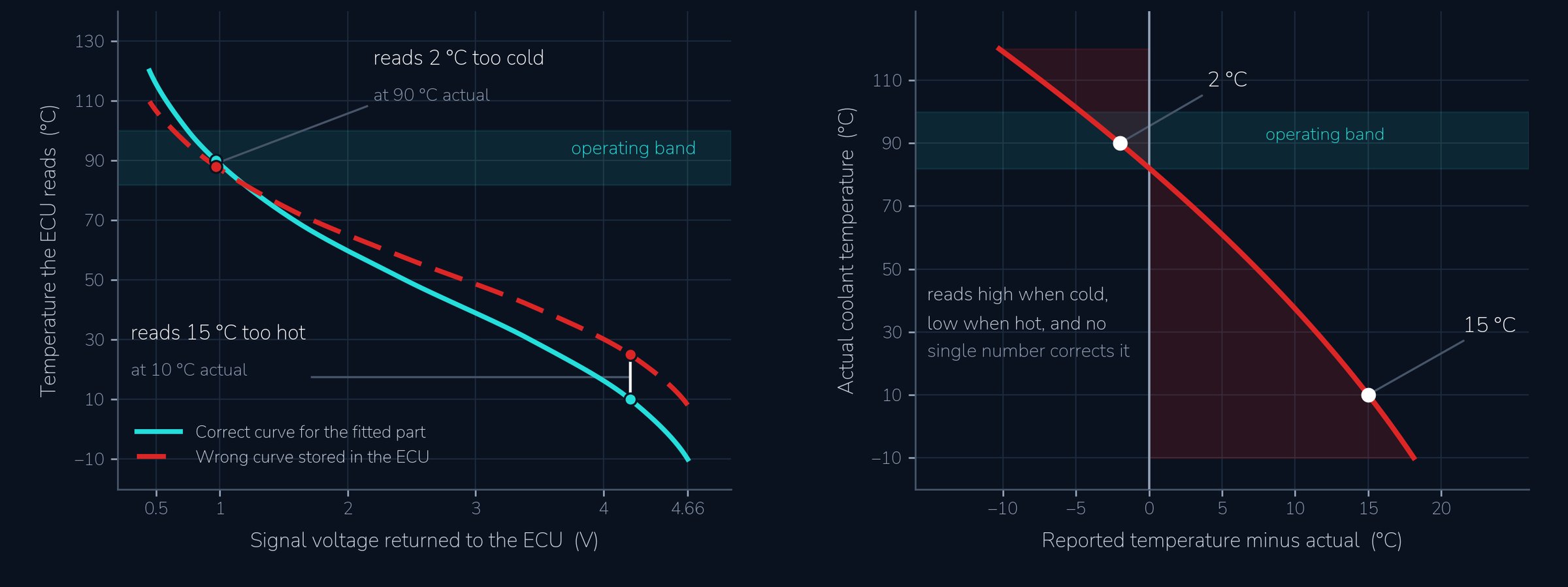
Because the relationship isn't a straight line, that difference is not the same size at every temperature. A curve that's two degrees out at 90°C (194°F) can be fifteen degrees out at 10°C (50°F), and it can be out in the opposite direction at the two ends. There is no single number you can subtract to correct it, and getting it right at one temperature tells you nothing about the others.
Now think about where you'd notice, and where you wouldn't. Your calibration work mostly happens when the engine is warm, in a narrow temperature band, and if the curve is accurate through that band then everything you tuned on the dyno will be built on a reasonable representation of the engine's actual temperature. The engine runs properly when it's warm, the logs look right, and the calibration is genuinely finished for the conditions you tested it in.
When the sensor calibration is off you can get an engine that behaves oddly on startup and behaves perfectly once it's warm. Startup fuelling scheduled for a temperature the engine isn't at, so it floods or won't catch. An idle target picked from the wrong point on the curve, so it holds a fast idle long after it should have come down, or drops to the warm target while the engine is still cold and stumbles. Enrichment tapering out too early or hanging on too long.
Here's the part that catches people out. Every one of those symptoms looks like a problem in the tables and, in the limited window of cold start tuning, you might go into the startup fuel tables and add fuel for example, to correct a lean condition. It would work, because you'd be fixing the issue and giving the engine more fuel, but now the table is wrong in a way that exactly cancels the curve error, on one particular morning, at one particular operating temperature. Come back on a colder day and it's wrong again, in a different direction, and you're back in the table. Swap the sensor with a new one and the whole calibration could be off.
A conversion error doesn't present as a sensor problem. It presents as a calibration problem in whichever table you happen to be looking at, and correcting the table bakes in the error at that temperature. Do this enough times across all engine temperatures and your calibration is now reliant on that specific sensor with that specific conversion curve.
There's one free check that's worth doing before any of that. Leave the engine off long enough that it is at ambient air temperature, and then read the coolant temperature. It should read the same as ambient. If the car has been sitting overnight at 15°C (59°F) and the ECU reads 5°C (41°F), the conversion is wrong at that end of the curve and every cold-side strategy is working with that error baked in. It's one point rather than the whole curve, and it won't tell you anything about 60°C (140°F), but it takes ten seconds and it's the difference between tuning a table and tuning around a bad number.
Before you start correcting anything that references coolant temperature, confirm the number that the ECU is telling you is real. It underpins so much of our calibration work that it's worth a little extra time to set this up correctly before tuning the engine and baking in a whole lot of errors and unpredictable engine behaviour across the temperature range.
If there's a specific topic or area you'd like us to cover in a future article or video, we'd like to hear about it. Send your requests through to support@efimastery.com and we'll add them to the list.
Key points
- The sensor doesn't send a temperature. It sends a voltage, and a curve in the calibration converts that voltage into the number every coolant temperature referenced table then works from.
- Almost all coolant sensors are NTC thermistors, meaning resistance falls as temperature rises and vice versa.
- Coolant temperature is a simplified model of the metal and wall temperatures that actually govern fuel evaporation, flame development, and friction, and it's the cheapest reliable measurement that tracks them effectively.
- The resistance to temperature relationship is non-linear, which is why the ECU carries a curve rather than a scale and an offset, and why two sensors that agree at operating temperature can be a long way apart at the extreme ends of the temperature scale.
- Startup fuelling, warm-up enrichment, idle target, ignition timing correction, charge heating correction, fan trigger, and the hot-side protections are all coolant temperature referenced. Make sure the sensor calibration data is accurate.
- A conversion error differs in magnitude at every temperature, so no single offset can correct it. Getting it right at one temperature says nothing about the rest of the range.
- A conversion error shows up as a problem in whichever tables you're tuning, not as a sensor problem. With the engine cold and sitting at ambient, the reading should be ambient. Confirm that before you correct any tables or begin a tuning session where practical. It's a good baseline check.
Knowing what the sensor is, and what relies on it, is the starting point. Working out what each input is measuring, how the ECU turns it into a decision, and how to plan all your inputs, is what Stage 2 covers in depth in the Hardware Competence, Calibration Competence, and EFI Master Programs. Take the free assessment to find out which one fits your goals.
Find Your ProgramGet notified of new articles
One article per week on EFI fundamentals, calibration principles, and diagnostic thinking. No spam.
You're subscribed. We'll let you know when new articles are published.