Engine speed and position information comes from two signals, a crankshaft sensor and, on most modern engines, a camshaft sensor. This article covers what each sensor tells the ECU, why the trigger wheel has a deliberate gap in it, and what the common trigger faults are actually telling you. A crank sensor is needed on every engine that uses the ECU to trigger the ignition outputs, while the cam sensor is technically optional, depending on your injection and ignition stratgy, the majority of the time you'll want to run one. Read on to understand why.
What the crank signal actually tells the ECU
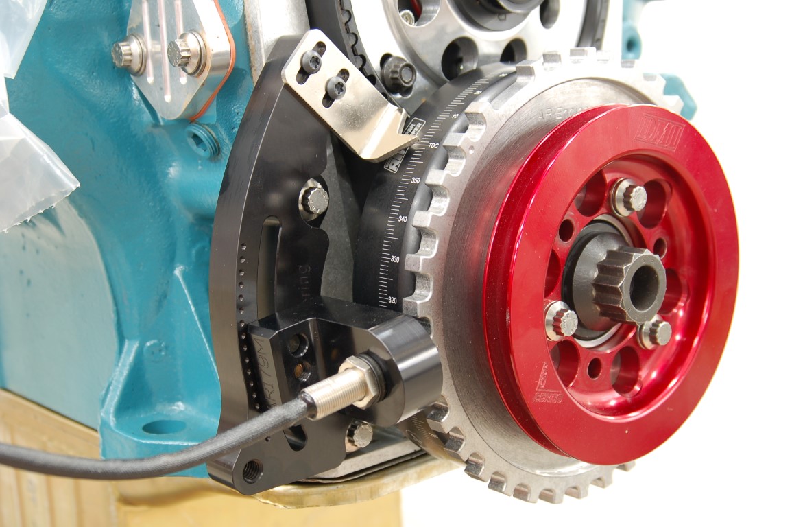
The crankshaft sensor reads a toothed wheel that turns with the crank. Wheels vary by the number of evenly spaced teeth. The count is usually chosen to divide evenly into 360, such as 12, 24, 36, or 60, so each tooth represents a whole number of crankshaft degrees. For example, a 60 tooth wheel has 6 degrees between each tooth on the wheel (360/60). Each tooth produces a pulse as it passes the sensor, so two pieces of information come out of that pulsed datastream.
The first is engine speed. How fast the pulses arrive is a direct measure of RPM, and RPM is the reference almost every other calculation runs against, including the fuel and ignition calculations.
The second is crank position, though only in a limited sense. The even spacing tells the ECU how far the crank has turned since the last tooth. The resolution depends on the tooth count, so a 60-tooth wheel reports engine position every 6 degrees. That's fine enough to place an ignition event, which is why the ECU times its fuel and spark from the crank signal rather than the cam. The crank is the high-resolution clock. A wheel with 12 teeth will only report crank position every 30 degrees, so you can see, in contrast to the 6 degrees of a 60 tooth wheel, a 12 tooth wheel just has a lot less resolution and reported pulses per crankshaft revolution.
Two sensor types read the crankshaft trigger wheel, and the difference matters when a signal goes marginal. An inductive sensor generates its own voltage as each tooth passes, and that voltage climbs with engine speed. A weak sensor can therefore be strong enough to run the engine above a certain RPM, yet too faint to read reliably at cranking speed. A Hall effect sensor is powered by the ECU and switches between two fixed voltage levels, so its output is a clean square wave at any RPM, meaning the output from a Hall Effect sensor is consistant across the RPM range. Their wiring and noise behaviour differ, which is a seprarate topic of its own. The signal they each hand the ECU serves the same ultimate purpose though, to stream the existance of tooth edges to count and time.
The crank signal tells the ECU where the engine is and how fast it's turning. What it can't tell the ECU, on its own, is which half of the cycle that position belongs to.
Why one crank revolution isn't enough
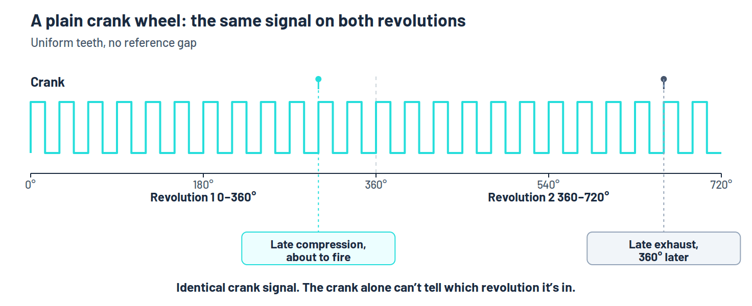
A four-stroke engine takes 720 degrees to complete one fuell engine cycle of intake, compression, power, and exhaust. The crank itself only turns through 360 degrees per revolution, so a plain toothed wheel looks the same on the first 360 degrees as it does on the second rotation through 360 degrees. The sensor reads an identical run of teeth both times around.
That leaves the ECU with two possibilities for any given crank position. In one, the cylinder it's tracking is finishing compression and about to fire. In the other, exactly 360 degrees later, that same cylinder is partway through its exhaust stroke. The crank reads the same in both, but the engine is in a completely different part of its cycle.
For a wasted-spark ignition system that ambiguity is harmless, because the spark that lands on the exhaust stroke is thrown away by design and the engine runs regardless. But the moment you want to inject fuel against a particular cylinder's intake event, or fire a single coil only when that cylinder is on compression, the ECU has to know which of the two revolutions it's in. It needs the phase of the cycle, not just the angle of the crank.
What the cam signal adds
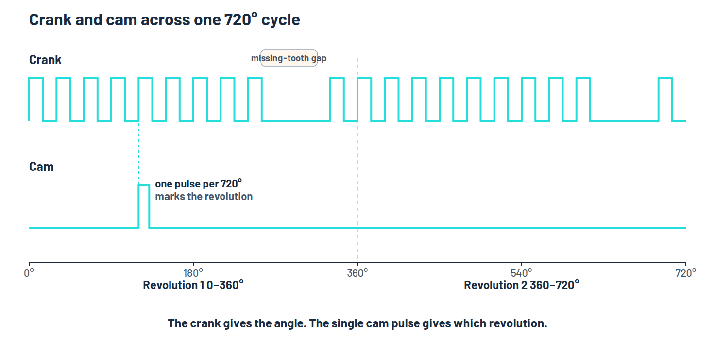
The camshaft turns at half crankshaft speed, one revolution for every two of the crank, so it completes exactly one turn per engine cycle. A sensor reading a single feature on the cam therefore fires one pulse every 720 degrees, a marker that falls in one of the two crank revolutions and never the other.
That one pulse is enough to break the tie. Once the ECU sees it, it knows which revolution it's in, and the crank signal stops being ambiguous from there on. The cam gives it the phase, the crank gives it the angle within that phase, and together they tell the ECU which cylinder is on which stroke, refreshed on every tooth.
This is why the cam sensor is often called a phase sensor or a sync sensor. Its job is identity, not precision. It only has to be accurate enough to fall in the right crank revolution, which is why a single feature (cam lobe, tooth, or other feature) read by a simple sensor does the job. The crank carries the resolution, the cam carries the answer to which half.
It's also why true sequential injection and coil-on-plug ignition depend on the cam signal, while batch injection and wasted spark don't. Sequential fuelling and coil-on-plug ignition systems are both per-cylinder decisions, and you can't make a per-cylinder decision until you know which cylinder is which. Without the cam, the ECU can still run the engine, but only by treating the cylinders in groups. That's all the crank can support on its own.
Why the wheel has a gap
Look closely at a typical crank trigger wheel and it's rarely uniform. A 60-tooth wheel usually has two teeth missing, a 60 minus 2 pattern, and a 36-tooth wheel commonly has one missing, a 36 minus 1. The gap is deliberate, and it fixes a problem having even tootth spacing creates.
Evenly spaced teeth measure how far the crank has moved, but they give the ECU no fixed point to measure from. Every tooth is identical to the next, so counting them gives a change in position, but no concrete referece point. It's like having a ruler with evenly spaced marks but no zero.
The gap is what supplies the zero. With two teeth absent, the sensor sees an interval about three times longer than a normal tooth spacing, and the ECU reads that stretched gap as its reference point. From that mark it can number every tooth that follows, and the previously uniform series of pulses become an absolute scale that can be referenced against. The reference typically isn't top dead centre itself. The wheel is set so the gap falls at a known angle to TDC, and the ECU works back to the true crank angle from there. That dependence is why physical alignment and timing the engine matters so much in the early stages of calibration. The ECU trusts that the reference sits exactly where it's been told, and measures everything else from it.
The gap isn't a flaw in the wheel. It's the one feature that turns a uniform pulse train into an absolute position the ECU can trust.
Sync, and why nothing fires without it
Sync, short for synchronisation, is the state where the ECU has fully resolved engine position. On a crank-only setup that means it's found the gap and numbered the teeth. On a sequential setup it also means it's seen the cam pulse and settled which revolution it's in. Once that's done, the ECU knows where the engine is and can start timing events against it.
Up to that point it knows very little. Through the first part of cranking it's still reading teeth and waiting for the gap, and on a sequential setup it's waiting for the cam edge too. That's why an engine never fires on the very first tooth the sensor sees. It has to collect enough of the pattern to be sure of position. On a crank-only setup that can happen within a revolution. A sequential setup also has to catch the cam pulse, and that only comes round once every 720 degrees, so full phase sync can take up to two crank revolutions. It's part of why an engine spins for a moment before it catches. If sync is never reached, nothing fires at all. The starter turns, the fuel pump may even prime, but with no trustworthy position the ECU keeps fuel and spark shut off and mis-calibration of these sensors, or installation issues, are a common cause of no-start faults. To speed up the process of starting the engine, many ECUs will start in group-fire and wasted spark mode, and then switch to sequential operation once the engine is running and the cam signal or it's equivalent is operating and reporting it's signal.
Until the ECU has resolved position, it has nothing to time fuel or spark against, so it holds both off. No sync, no start is the system protecting the engine, not failing to try.
When the trigger setup is wrong, and what it's telling you
Trigger faults tend to present as a few recognisable patterns, each one pointing at a different part of the chain. Treated as information rather than as the ECU being temperamental, those patterns are most of how we diagnose these faults.
A clean no-start, with the engine cranking normally and both fuel and spark absent, usually means sync was never reached. The position signal isn't arriving clearly enough for the ECU to find its reference and number the teeth, so the engine stays dark.
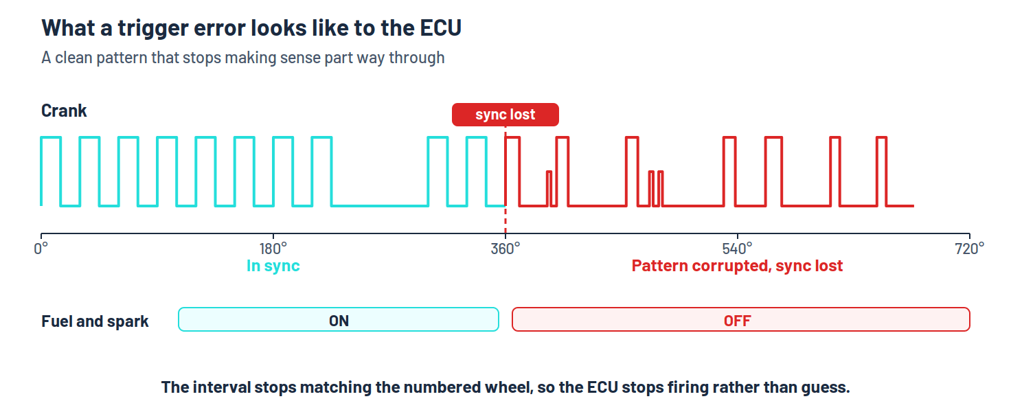
A sync or trigger error logged while the engine's running means the ECU had position and then lost confidence in it. Something in the tooth pattern didn't fit, maybe a count that came up short, or an interval that didn't match what the numbered wheel predicted. Noise on the signal, a marginal sensor air gap, debris on the wheel, or a cracked tone wheel will all do that. The ECU's response is deliberately conservative. Rather than fire against a position it no longer trusts, it raises the error and, depending on how bad it gets, drops into a limp mode or shuts down. It won't guess, because guessing wrong would put spark into the wrong part of the cycle, which can lead to engine damage.
A trigger error isn't the ECU being fussy. It's telling you the position signal has stopped making sense, and it won't fire against a position it can't trust.
The most dangerous fault raises no error at all. If the offset is set wrong, or the wheel sits a tooth out from where the ECU believes it is, sync is still reached and the engine still runs, but the ECU's idea of crank angle is shifted, or offset, from actual engine position. Every ignition event lands at a different true angle than the figure on the screen, so the timing sits quietly under advanced or over advanced across the whole map, carrying all the knock risk and lost output that implies. Nothing in the software flags it, because the ECU is doing exactly what it was told. It's why the offset has to be confirmed against the engine's real position with a timing light, rather than blindly trusting a number. Getting this wrong is more dangerous than a fault that simply stops the engine, and especially if you're grabbing timing numbers from a random forum post and blindly trying them out.
Key points
- The crank signal carries two things, engine speed from the pulse rate, and crank position based on the resolution of the tooth spacing. It's the high-resolution clock the ECU times fuel and spark against.
- A four-stroke cycle is 720 degrees, two crank revolutions, and a plain wheel looks the same during both, so the crank alone can't tell which part of the cylcle it's in.
- The cam signal occurs once per cycle and identifies the revolution, and therefore which cylinder is on which stroke. That phase information is what sequential injection and coil-on-plug ignition depend on, while batch injection and wasted spark will run on the crank signal alone.
- The missing teeth form a reference mark, and without it the ECU can measure a change in position but has no fixed zero. The gap sits at a known angle to TDC, and the ECU numbers every tooth from there.
- Sync is the state where position is fully resolved. Until the ECU reaches it, no fuel or spark is delivered. No sync, no start.
- Trigger faults read as information. A clean no-start is usually sync never reached, a running trigger error is position lost mid-cycle, and a wrong offset is the dangerous one, because the engine runs while its real timing is shifted from what's commanded, with no warnings or errors displayed on the laptop.
Related Resources
Further reading
- Robert Bosch GmbH, Gasoline Engine Management: Systems and Components. Crankshaft and camshaft sensing, engine synchronisation, and sequential injection.
- Robert Bosch GmbH, Bosch Automotive Handbook. Inductive and Hall effect speed and position sensors.
- William B. Ribbens, Understanding Automotive Electronics. Crankshaft position measurement and engine control fundamentals.
- Tom Denton, Automobile Electrical and Electronic Systems. Sensor types, signal conditioning, and fault diagnosis.
Crank and cam signals, sync, and reading what a trigger fault is telling you all come down to understanding what your ECU is doing with its inputs, which is the ground Stage 2 covers. That understanding is built through a structured progression in the Hardware Competence, Calibration Competence, and EFI Master Programs, with the depth to carry across different engines, trigger patterns, and the faults you haven't seen yet, rather than a setup you follow once. If you're not sure which one fits your goals, take the free assessment and it'll point you in the right direction.
Find Your ProgramGet notified of new articles
One article per week on EFI fundamentals, calibration principles, and diagnostic thinking. No spam.
You're subscribed. We'll let you know when new articles are published.