This article covers how much a wastegate has to flow, what sets that requirement, and what happens across the engine when the flow capacity of the wastegate is insufficient for the job.
The wastegate needs to flow the leftovers
Exhaust gases leave the exhaust ports and pass through the turbine, where the turbine extracts energy from the gas as shaft power. That shaft then directly drives the compressor wheel which is connected at the other end.
With the wastegate valve shut, all of the exhaust goes through the turbine. Open the valve and part of the available mass flow goes around the turbine and straight into the exhaust downstream, doing no work on the turbine. One thing to remember is that a wastegate only ever reduces the energy reaching the turbine from the maximum available energy coming from the exhaust ports.
When boost pressure is stable, the turbine is producing exactly the power the compressor is consuming in order to maintain that particular boost level. The turbine uses the required mass flow needed to make that shaft power, and the wastegate flows everything left over. Basically, the bypassed fraction of available mass flow is whatever the turbine doesn't need at that particular operating point.
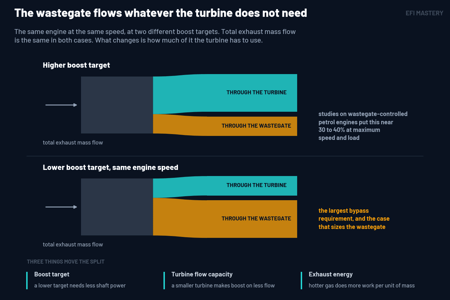
Three things influence the fraction of mass flow being bypassed around the turbine. The first is your boost target. For a given setup, a higher boost target needs more of the exhaust going through the turbine, but with a lower target less shaft power is needed and so more of the exhaust goes through the wastegate instead. The second thing is the turbine's flow capacity, meaning how much mass flow the turbine passes at a given expansion ratio. A small turbine runs a higher expansion ratio for the same flow, so a small turbine can generate more boost at the same flow as a larger turbine. Because of this, more exhaust will be bypassed around the turbine through the wastegate. The third influence on mass flow through the wastegate is exhaust energy. Hot gas does more work per unit of mass, so the turbine needs less mass flow to make the same shaft power.
For a sense of scale, studies on wastegate-controlled turbocharged petrol engines show around 30 to 40 percent of the exhaust going around the turbine at maximum speed and load, and while I wouldn't strictly size your wastegate on that number alone, it shows that it's a fairly large fraction of the total mass flow, rather than just a few percent.
The case that demands the most from the wastegate isn't your highest boost target. It's the lowest boost you intend to hold at high engine speed. Where the compressor draws the least power (low boost), the turbine needs the least flow, and the largest fraction of the exhaust has to go through the wastegate. A wastegate with enough flow capacity at your maximum boost target can run out of flow at your lowest target.
The bypassed fraction isn't a property of the wastegate. It's whatever the turbine doesn't need to make the boost you're targeting.
Where the wastegate runs out of flow
A wastegate has a maximum flow capacity, just like any pipe or outlet. With the valve fully open, the bypass passes whatever mass flow the open area and the pressure across the valve allow. Any flow above this that the engine produces ends up going through the turbine.
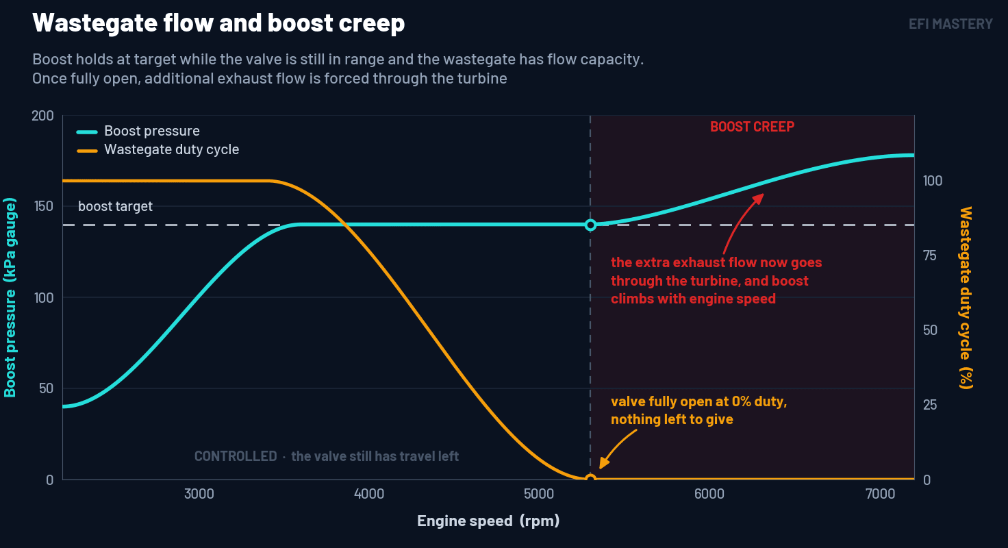
This is where boost creep comes in. Boost holds at target while the valve still has the ability to open further, then steadily climbs as engine speed rises and the additional exhaust flow is forced through the turbine. In the case that you are running electronic boost control, you've reached the mechanical limits of the system, and no amount of changes in the calibration tables will fix it.
Where the wastegate is mounted changes how much total capacity is available in the first place. An internal wastegate is built into the turbine housing and shares the housing's flow path, which packages well and suits most builds up to a moderate level, but is usually not enough in higher horsepower and flow situations. An external wastegate typically mounts on the exhaust manifold, normally at the collector where the runners meet, and can be sized independently of the turbine housing, which is why the larger sizes appear on high output engines and why an external wastegate gives more control over how much exhaust reaches the turbine.
Once the valve is fully open, boost is set by hardware limitations. No calibration changes will bring boost back to target.
An undersized wastegate will show as increased exhaust pressure
Exhaust that can't get through the wastegate still has to leave the engine, so the flow goes through the turbine. A turbine will flow a given mass flow at a given expansion ratio, which is the ratio of pressure before the turbine compared to pressure after it. Pushing more mass flow through the same turbine raises the expansion ratio, and because the downstream pressure is close to atmospheric, the increased expansion ratio shows up as an increase in turbine inlet pressure (or drive pressure), sitting in the exhaust manifold.
Although we need this difference in pressure to drive the turbine wheel, there's a point where more turbine drive pressure has increasingly negative consequences. This can be seen when trying to achieve high boost pressures and high flow rates using a turbo that's too small for the job. Turbine inlet pressures continue to climb and the turbo's effective operating range is impacted as a result. Engine efficiency and top end performance are affected as well.
Three things change as exhaust manifold pressure rises, and all three tend to compound each other.
Pumping work, which is the work required to move air into and out of the engine, goes up, because the piston pushes the exhaust out against the pressure in the exhaust manifold. On one boosted research engine this was as much as 5 to 6 percent of brake output.
The second thing is that cylinder filling goes down. Volumetric efficiency on the same research engine fell about 4 percent for each 60 kPa (~9 psi) of additional exhaust manifold pressure. Higher pressure in the exhaust manifold during valve overlap pushes burnt gas back toward the cylinder rather than letting fresh charge scavenge through, so less air is trapped in the cylinder, and what is in the cylinder is diluted with hot residual gas.
Knock margin can also reduce because the extra residual gas raises charge temperature, which is one of the variables that moves the knock threshold. Knock-limited combustion phasing on that engine came back by about 2 degrees of crank angle across the pressures tested. Together, the three effects took around 10 percent off the engine's brake output between the highest and lowest exhaust pressures tested.
Those figures come from a single engine done in a lab and while the specific numbers won't transfer to every build the trends do, and none of the three compounding effects of increased turbine inlet pressure presents as a wastegate problem in the data. You see an engine down on power, a VE table that needs adjusting down, and knock arriving at less advance than before.
Of course, if you retard timing to move away from knock you can end up with additional pressure in the exhaust manifold which is what was causing the problem in the first place. Additional turbine inlet pressure increases the expansion ratio as well and actually drives the turbine harder, which can then cause or worsen any overboost problem you might be seeing. Everything's interconnected and none of it is fixed with a laptop.
Flow the wastegate can't pass raises exhaust manifold pressure. That pressure adds pumping work, reduces trapped air, and lowers the Knock Limited Spark Advance (KLSA).
The spring sets your minimum boost target
Everything so far has been about how much the wastegate can flow. What decides when the valve opens and closes is a separate mechanism, and how this works, as well as how this influences your obtainable boost targets, is worth understanding.
A pneumatic wastegate is held shut by a spring and opened by boost pressure acting on a diaphragm. The force on the diaphragm is the pressure multiplied by the area of the diaphragm, so the force increases as boost pressure rises, and the valve starts to open when the force applied to the diaphragm overcomes the spring force.
This is why you can't regulate boost pressure to a level that is lower than the spring pressure in the wastegate. Because the pressure exerted by the spring and the pressure exerted on the diaphragm are two sides of the same system, the point of equilibrium between boost pressure and spring pressure ultimately determines the regulated manifold pressure, assuming everything is working as it should. If boost pressure rises in the system, the valve opens further, reducing the exhaust mass flow going through the turbine, reducing the available shaft power to drive the compressor wheel, and boost drops away again. As boost pressure drops, the wastegate valve starts to close again as the spring pressure has more influence on the force balance. This flows more exhaust back through the turbine and increases boost again. This delicate dance is precisely how a consistent boost level is able to be maintained in a pneumatic system.
This mechanism is what we are manipulating with typical boost control methods for pneumatic wastegates, which we use to move the equilibrium point beyond the set spring pressure. The first method bleeds part of the reference pressure away before it reaches the diaphragm, usually through a solenoid although it can be a simple bleed valve, so the intake manifold has to reach a higher pressure before the force on the diaphragm overcomes the spring. We are artificially reducing the pressure that is being applied to the diaphragm so by the time there is a force balance across the diaphragm we have increased boost pressure beyond the wastegate spring pressure.
Another method feeds regulated pressure to the spring side of a dual-port actuator, so the pressure on the diaphragm has to increase further before the valve moves. So in addition to artificially reducing pressure on the diaphragm side, you also add a constant pressure to the spring side which adds to the spring pressure, giving us much higher boost levels that can still be controlled with reasonable accuracy. In both cases, for pneumatic systems, the boost pressure range is always going to be, at minimum, wastegate spring pressure, and otherwise any desired value above this up to the hardware limits of your engine and turbo system.
A bigger wastegate adds bypass capacity. It doesn't lower the regulated boost you can hold, because the spring determines your lowest boost level, not the valve flow capacity. Of course, if you have a wastegate that is too small, then a lack of flow may cause your minimum boost level to be higher than the spring pressure, and by properly sizing the wastegate for the application you may be able to reduce your minimum boost target, but only as far as the spring pressure will allow. Once you are controlling boost at spring pressure, this is the minimum boost the system will run.
A pneumatic wastegate regulates upward from its spring pressure and can never regulate boost below that pressure.
An electronic wastegate provides additional control
An electronic wastegate removes the limitations of the spring/diaphragm equilibrium coupling. Instead of a diaphragm and a spring, a motor drives the valve directly to a commanded position, and a position sensor on the actuator reports where the valve actually is. The ECU drives the actuator using the same kind of output that drives an electronic throttle body, and the control loop will change the valve position based on the desired target directly.
Nothing in that arrangement sets a minimum. No spring holds the valve shut and no boost reference sets when the valve moves, so there is no lowest boost the hardware will regulate at. The valve can be commanded part open at light load to hold a low target, or held shut well past the pressure a spring would be capable of withstanding. Because the wastegate valve position is now directly driven, both the speed and accuracy of wastegate movement is improved at all operating points, so you have much more flexibility with boost targets and greater consistency of control.
What doesn't change, though, is flow capacity. It can only flow what the open area allows, so everything in the first half of this article applies to an electronic wastegate as well. Putting fancy electronics on a pipe that's too small doesn't fix the size of the pipe.
An electronic wastegate removes the spring/diaphragm limitations and improves control and consistency. The flow limit stays exactly the same.
A wastegate is commonly, and incorrectly, sized against a boost number, and boost is not what sets the sizing requirement. The requirement comes from understanding the mass flow left over, once the turbine has extracted what it needs to drive the compressor. That leftover is largest at the lowest boost you intend to hold at high engine speed. Cover that case and higher boost targets are already covered. If you want to run low boost, then you need to bypass a lot of exhaust flow relative to targeting high boost, where you need shaft power to spin the compressor wheel and the exhaust flow moving through the turbine, not the wastegate valve.
Key points
- A wastegate controls boost by letting part of the exhaust mass flow bypass the turbine.
- The bypassed fraction is whatever the turbine doesn't need to drive the compressor to your target, so the fraction moves with the boost target, the turbine's flow capacity, and the energy in the exhaust.
- The largest bypass requirement comes at the lowest boost you intend to hold at high engine speed, not at your peak target.
- Once the valve is fully open the wastegate can do no more, and everything beyond that goes through the turbine. That is boost creep.
- An internal wastegate shares the turbine housing and is often not enough at higher flow requirements. An external wastegate at the collector can be sized independently of the housing and is used to re-gain control of boost.
- Flow the wastegate can't pass raises exhaust manifold pressure, which adds pumping work, reduces trapped air, and brings the knock limit on at less advance. This can't be fixed with a laptop.
- A pneumatic wastegate cannot regulate below its spring pressure, and every control method used on a pneumatic wastegate system increases boost pressure from spring pressure.
- An electronic wastegate is commanded to a position and isn't limited by spring pressure, but the flow capacity of the valve is unchanged.
- If boost climbs away at high engine speed with the controller already diverting maximum flow, the limit is flow capacity in the wastegate, and no calibration change will move that limit.
If there's a specific topic or area you'd like us to cover in a future article or video, we'd love to hear from you. Send your requests through to support@efimastery.com and we'll keep you posted.
Related Resources
Knowing what size the wastegate has to be is an important part of turbocharger setup. Building the calibration on top of that hardware, from a stable open loop base map through to closed loop control, is what Stage 6 covers in depth in the EFI Master Program. Take the free assessment to find out which Program fits your goals.
Find Your ProgramGet notified of new articles
One article per week on EFI fundamentals, calibration principles, and diagnostic thinking. No spam.
You're subscribed. We'll let you know when new articles are published.